What is variable frequency drive circuit: its operation, types and Vfd wiring schematic Vfd wiring schematic
VFD or Inverter Drive Power Component Schematic - YouTube
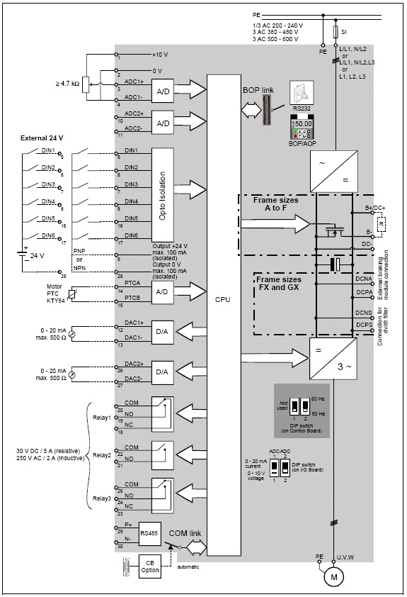
Vfd circuit diagram schematic wiring motor understanding drive variable frequency components full vfds output rectifier fig resolution click picture Vfd diagram ac drives wiring operation motor principles circuit variable frequency panel drive schematic dc pulse width inverter convert phase Single phase variable frequency drive schematic
Control circuit diagram of vfd
Vfd controlled by switchesVfd circuit drive types operation working sourav gupta jan Vfd drive circuit diagram3 phase motor vfd circuit diagram.
Understanding vfd circuitVfd ac diagram drive block electric drives electrical typical dc electricaltechnology parts construction working variable converter frequency control power controller Phase circuits vfd circuit diagram variable frequency drive single wiring electrical motor speed homemade diy projects schematic ac control powerVfd inverter component.

Vfd circuit diagram explanation
Vfd (variable frequency drive)Best practices for vfd grounding Vfd variable speed motor drive ac diagram installation block switches controlled control frequency connected function phase drives controller terminals componentsVfd (variable-frequency drive) practical circuit diagram and schematic.
Vfd schematic diagram and controlWiring diagram for vfd Single phase variable frequency drive vfd circuitVfd start stop wiring.

What is a vfd?
Vfd schematic diagram and controlMotor controller What is vfd, how it works?Vfd circuit diagram pdf.
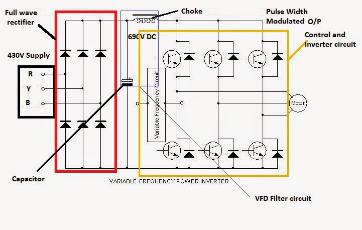
Vfd or inverter drive power component schematicVfd frequency electrical diagram motor control circuit drive igbt variable ac principle working drives schematic dc phase three operation voltage Variable frequency drive 3 phaseVfd variable inverter rectifier comprised.

[diagram] abb vfd wiring diagram picture schematic
What is a vfd?Vfd circuit diagram explanation Vfd diagram plc wiring control circuit schematic drive using ladder diagrams connectionsPrinciples of operation.
Variable speed drive block diagramWhat is ac drive? working & types of electrical drives & vfd The schematic of the vfd.Variable frequency drives explained.

Inside variable frequency drive (vfd) panel: configuration, schematics
Vfd grounding schematic drive practices motors pwm general figure pumpsandsystems[diagram] abb vfd wiring diagram picture schematic .
.

VFD | VFD Panel | VFD Panel Drawing | What is VFD Panel | VFD Panel

Vfd Start Stop Wiring

motor controller - Maximum output voltage of a basic variable frequency

What is AC Drive? Working & Types of Electrical Drives & VFD

What is Variable Frequency Drive Circuit: Its Operation, Types and
Control Circuit Diagram Of Vfd
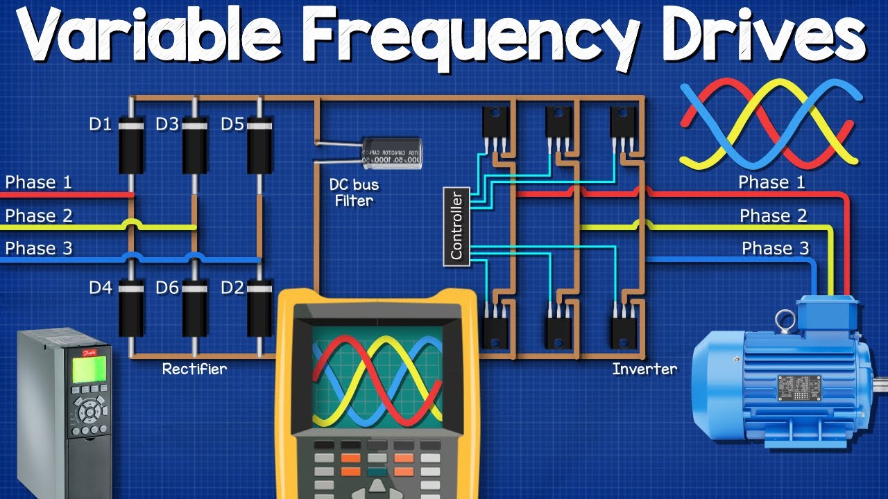
Variable Frequency Drives Explained - VFD Basics IGBT inverter - Bombofoods
